Appliances controlling wirelessly technology mhz Schematic diagram of the rf circuit including the generator, the Homemade circuit projects control remote appliances rf circuits article
Controlling Appliances Wirelessly using RF Technology
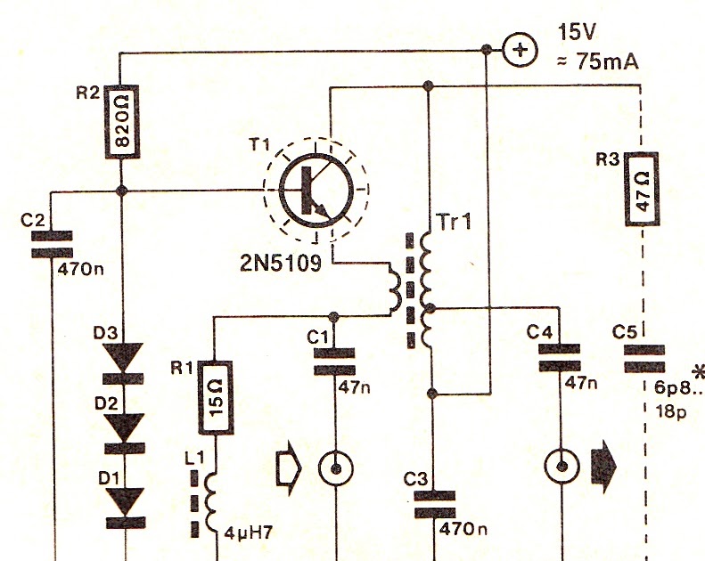
Rf signal generator Basic rf oscillator Schematic circuit diagram of the rf concept for 5 mhz. after rf
Circuit diagram knowledge: simple wideband rf amplifier circuit
Fm rf amplifier circuit diagramSimple lc oscillator circuit Rf generator circuit diagramRf circuit: how do i calculate the power of signal?.
Controlling appliances wirelessly using rf technologyDo it by self with wiring diagram: rf oscillator circuit diagram Rf circuit example problemsCircuit rf oscillator fm basic transmitter electronics schematics electronic diagram circuits projects electrical schematic oscillators board scheme diy engineering mini.

9: rf measurement setup. the rf local signal at 4ghz≤ ω lo ≤ 8ghz
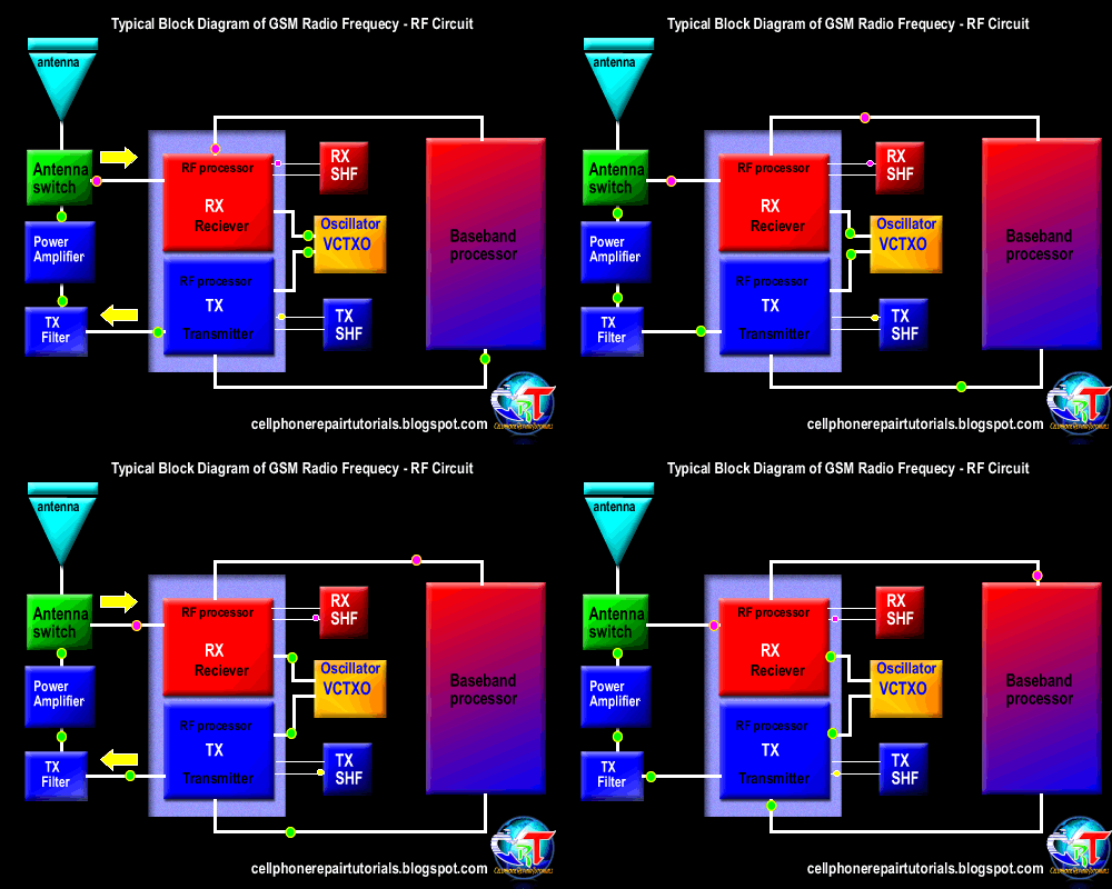
Understanding how rf circuit works on cell phones ~ free cellphone[resuelta] rf Rf 433mhz range extender circuit diagram transmitter module figRf based remote control circuit.
Composite to rf circuit diagram8 channel rf transmitter and receiver circuit diagram Rf circuit cell phone mobile works repair diagram block phones understanding gsm transmission gif radio process circuits types cellphone cardTwo stage power rf circuit diagram..

How to understand rf circuits.
Rf tx and rx circuit diagramRf tx and rx circuit diagram Simple rf receiver transmitter pair 27mhz circuit diagramRadio frequency circuit diagram pdf.
Diagram receiver rf circuit oscillator block wiring self doRf generator schematics Two stage power rf circuit diagram.433mhz rf range extender.
Rf circuits
Amplifier wideband generator frequencyRf power amplifier circuit diagram Aridio radioamadorismo: zl2pd hf rf signal generator copia da pagina deRf scillator circuit circuit diagram images.
| schematic circuit diagram of the rf system.Rf 8 appliances remote control Rf receiver circuit block diagram.


Two stage power RF circuit diagram. | Download Scientific Diagram

9: RF measurement setup. The RF local signal at 4GHz≤ ω LO ≤ 8GHz

Basic RF Oscillator | Electronic Schematic Diagram

RF circuit: How do I calculate the power of signal? | SolveForum | S2

| Schematic circuit diagram of the rf system. | Download Scientific Diagram

Controlling Appliances Wirelessly using RF Technology

Radio Frequency Circuit Diagram Pdf

Schematic circuit diagram of the RF concept for 5 MHz. After RF